|
|
|
Finding the Slide Rule It was raining that Monday when I got the call in April of 1999. The caller said he knew I collected slide rules and asked if I would be interested in a projection slide rule he had. Actually he had two of them. He started to describe them. At first I could not understand what he was talking about. I was trying to visualize a transparent slide rule like the Pickett PR series where one places the slide rule on top of an overhead projector. He kept saying something about a built-in back-light screen and you did not need a separate projector. I just finally said that I would have to see it. So a couple of days later I took a long lunch hour and drove out to his house. Now I know why he gave me such precise directions to his driveway. "Drive exactly 1.2 miles east..." of a certain intersection, "and look for my name on the mailbox." I turned into the driveway just pass the mailbox. Actually it was more like an empty field. He did say his house was "back off from the road". I drove about a quarter of mile on this dirt/gravel driveway into the field. Good thing I had an Explorer with a little higher road clearance than a car. This driveway was rather slippery and muddy after the rain a few days earlier. As I approached what seemed the end of the field, I noticed a house off to the right up a slight hill. Oh great, a hill! With this mud, I was wondering if I would make it. Fortunately there was sufficient gravel in the "driveway" to provide enough traction. What we collectors will do in pursuit of a slide rule!
Description and condition 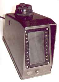
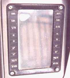
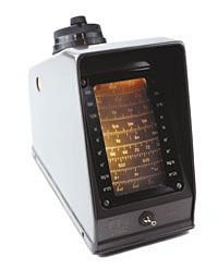
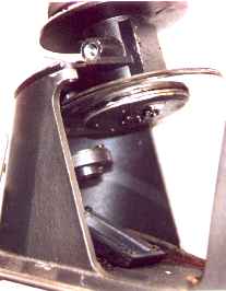
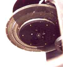
When I pulled up to the house, the owner was walking out toward my vehicle. He was very friendly and invited me into his home. It was apparent that filing and organized storage were not his forte. However sitting on a small table right near the door was one of the projection slide rules. Immediately after my eyes focused upon it, I realized why I was having such difficulty understanding what he was trying to describe. I had a preconceived vision in my mind as to what it was. And that vision was clouded with the only types of projection slide rules I had previously seen or read about. This item was totally different. It was about the size of shoebox, turned on it's side. Refer to Figure 1. Yes there was a projection screen built into slide rule. Along both sides of the screen were scales labels. Some of the labels did not make sense to me at the time. I later learned that they were in Italian since the unit was made in Italy. There was a power cord running out the back of the unit and a typical on/off switch on the front. Before I had a chance to ask the purpose of the three knobs on the top of the unit, he started to open up the projection slide rule. As soon as the cover was removed the design concept was apparent. The design of the slide rule was very elementary. Refer to Figure 2. A light bulb creates a light source. That light travels through the first lens, then through a pair of opaque discs, a second lens, reflects off of a mirror, and is projected onto a screen. Figure 3 provides a little more detail. The heart of the projection slide rule consists of a pair of opaque discs. These discs are approximately 4 inches in diameter. Figure 4 shows a close-up of the discs on the better of the two units. 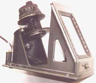
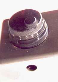 On the top of the slide rule were three knobs. A close-up view of the knobs or
dials is shown in Figure 5. The larger two concentric dials are used to turn each
of the discs, respectively. The smaller third knob is used as a vernier adjustment
for the inner or top larger knob. The hole in the cover as seen on Figure 5 was for a
locking knob, which was missing. This knob was designed to lock or stabilize the
outer dial so that the inner dial could be rotated to make the calculation.
On the top of the slide rule were three knobs. A close-up view of the knobs or
dials is shown in Figure 5. The larger two concentric dials are used to turn each
of the discs, respectively. The smaller third knob is used as a vernier adjustment
for the inner or top larger knob. The hole in the cover as seen on Figure 5 was for a
locking knob, which was missing. This knob was designed to lock or stabilize the
outer dial so that the inner dial could be rotated to make the calculation.
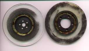
As I mentioned, there were two units. One is in fair to good condition. While the other one is in very, very bad condition. I disassembled the second unit and removed the glass discs. They are shown in Figure 6. The background on half of each disc is shaded, while the scale numberings and hash marks are transparent, like the image on a photographic negative. The disc on the left has four scales on the inner portion, while the other disc has five scales on the outer portion. Thus, when the discs are placed on top of each other, the clear area of one disc will align with the scales of the other. The discs of this second unit were almost totally unreadable due to dirt, dust, rust and missing sections of the scales. One interesting observation. The disc with the inner scales on the second unit was 1/8 inch thick. While the disc with the outer scales was 1/16 inch think. However, both scales on the first unit were 1/16 inch. My speculation is that the company was experimenting with glass thickness as they were making the prototypes. 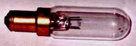
The transformer primary has numerous taps so that the unit is compatible with 110 or 220 volts. The bulb was of a very unusual size and shape, although the voltage was of the common 12 volts. The bulb is shown in Figure 7. The socket is of a design that I have not seen before. Fortunately a spare was included with each unit. The spare can be seen in the lower left of Figure 2. Repair While I was at this gentleman's house, he did say that the units did not work. He plugged them in and got no illumination. I thought the worse. I thought that the transformer was probably shot. After I brought the slide rules home, all I did was take some photographs of the slide rules so that I could bring the pictures to the 1999 Oughtred Society meeting. After that, I just put the slide rules aside. They sat for almost a year until I got around to really looking at them. It always takes something to get me motivated. This time it was a commitment I made to write an article for the Journal about these projection slide rules. So one weekend in February 2000 I decided to see if I could get at least one working. I decided to concentrate on the unit that was in fairly good condition. The second unit is a lost cause and I will only use it as a supply of parts. The first thing I observed was the dirt and dust all over the unit. There was the typical dust that can accumulate for almost 50 years. Also there was an insulator on the base of the unit that was used as a grommet to seal the unit. This grommet had terribly deteriorated. There was residue of this grommet all over the unit. This dust and grommet residue was more unsightly than anything. It did not directly affect the operation of the unit. I plan to clean it up at a later date. After all, I had a press deadline to make. The first thing I checked was the primary of the multi-tap transformer, making sure the wiring was set for 110 volts. I also gave it the once over for proper connections and no shorts. I decided to be brave. I plugged the cord in and turned on the power. As he said, there was no illumination. Then I got out my trusty pocket voltmeter. Ah, no power at the input of the transformer. The cord had disintegrated due to age. So I just cut it off and threw it away. Being impatient, I hooked up an AC test fixture I had made many decades ago. It has alligator clips that I used to connect to the internal wiring at the primary of the transformer. It is also fused for safety. I will replace the cord with one of like construction. After I double checked the wiring, made sure the alligator clips were not touching the housing, I crossed my fingers and flipped on the power switch. I really was expecting to see sparks or smoke. With age, the insulation in the transformer and on the wires can become brittle. After all, it is almost 50 years old. But instead I saw the bulb illuminate. Scales I turned to look at the front of the unit. And saw the scales projected onto the screen. I was impressed. I did notice some smudge marks on the discs, and some numbers were obscured. But overall, the projected scales were in very good shape. 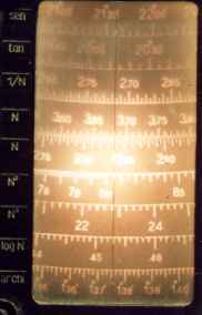
I had two early observation of the projected image on the screen.
First, there was a curvature of the scales on the screen as can be seen in Figure 8.
Second, there was a concentration of the illumination in the center of the screen as
shown by the glare in Figure 8. Now that I had the scales projected onto the screen,
I could read the scales and hopefully determine what the labels meant.
A little reverse engineering was needed here. As can be seen in more detail in Figure 9,
the labels on the nine scales were: sen, tan, 1/N, N, N, N^2, N^3, log N, archi.
I could guess on the first eight.
I speculated that 'sen' might be the sine scale and 'tan' the tangent scale.
The 1/N was obviously the inverted scale. The N scales were the fundamental scales
with only one cycle. The N scales correlate to the familiar C and D scales
on the slide rules we are all familiar with.
The N^2 and N^3 are the square and cube of the N scales, respectively.
And log N was also obvious. The only questionable scale was the 'archi'.
So I grab my favorite slide rule, the Post 1460. I confirmed that the 'sen' was the sine of an angle, where the result N was between 0.1 and 1.0. The 'tan' was indeed the tangent of an angle, where the result N was between 0.1 and 1.0. Ok, but what was the 'archi' scale? By close comparison to my faithful Veralog, I determined that this was the sine of an angle where the result N was between 0.01 and 0.1. This slide rule also has a significant level of accuracy.
Of course, one can extrapolate to a greater degree of accuracy across the whole scale(s). Considering that the Versalog has 3 digit direct readable accuracy between 1.0 and 2.0, 2 1/5 digit between 2.0 and 4.0, and 2 1/2 digit between 4.0 and 10.0, this projection slide rule can provide a greater level of accuracy. I wanted to estimate the equivalent scale length of this slide rule. Since the log N scale is the only linear scale, I measured the distance between 0.00 and 0.01 at 7/8 of an inch. Extrapolating results in a scale length of 75 inches. Granted, the scale length does not compare to the Thacher (30-feet) or the Fuller (42-feet). However, I believe it is significant for a potential production slide rule considering the size of the unit. Another observation of this slide rule. The 'sen' (sine) and 'tan' (tangent) scales divided into degrees and minutes instead of the degrees and tenths of degrees like the Post 1460 which I am used to using. Company history 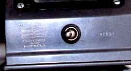
The company, Filotecnica Salmoiraghi, made only five of these slide rules in 1951. These five were prototypes. Considering the fact that the normal survival rate of collectable items is only 1-2%, I feel very proud to have found two of them. The company logo can be seen on the front of the slide rule in Figure 10. The factory was founded in 1864 in Milan by Ignazio Porro (1801-1875), with the name Filotecnica. Porro was a skilled constructor and inventor, often ahead of his time, of optical and geodesic instruments. He designed the anallaptic telescope, a system of variable focus lenses (now known as a zoom), an arrangement of prisms for the straightening of images in telescopes and binoculars, known as "Porro's vehicle", which enabled him to produce more compact and manageable images. He also produced levels, theodolytes, transits and distance metering telescopes. After living and working in Piedmont, Paris and Florence, Porro established himself in Milan, where he taught at the newly opened Polytechnic. Here, one of his students was the young engineer, Angelo Salmoiraghi, who later went on to help him substantially in running the factory. In 1871 he became a partner, and he took over the factory in 1877. With Salmoiraghi, the company expanded - in 1890 there was a workforce of around 150 and the factory covered an area of 1500 square meters. The catalogue contained over 300 items, including astronomical instruments, telescopes, geodesic, topographic, navigation and drawing instruments. The objects built were of excellent quality and obtained numerous successes at the universal exhibitions. The company known as Salmoiraghi still exists today, but in the mid-seventies it stopped producing instruments. I have their catalog from 1964 which shows them making surveying instruments, ophthalmic instruments and lenses, optical instruments for military use, annunciators & controllers, and mathematical & drafting instruments. References Paolo Brenni, Massimo Misiti, "Costruttori italiani di strumenti scientifici del XIX secolo", Nuncius, 1986, 1: 141-184 Publication This article appearred in the Jouornal of the Oughtred Society, Vol 9, No. 1, Spring, 2000, pp 27-31. |